- 您现在的位置:买卖IC网 > Sheet目录342 > MC34844EP (Freescale Semiconductor)IC LED DVR BACKLIGHT 10CH 32QFN
�� �
�
�COMPONENTS� CALCULATION�
�C� Comp1� =� --------------------------------------------------------�
�33� � 10�
�V� SLOPE� � 5�
�C� Comp2� =� ---------------------------�
�2�
�f� Cross� ×� R� Comp� ×� π� ×� 2�
�G� M�
�6.28� � F� SW�
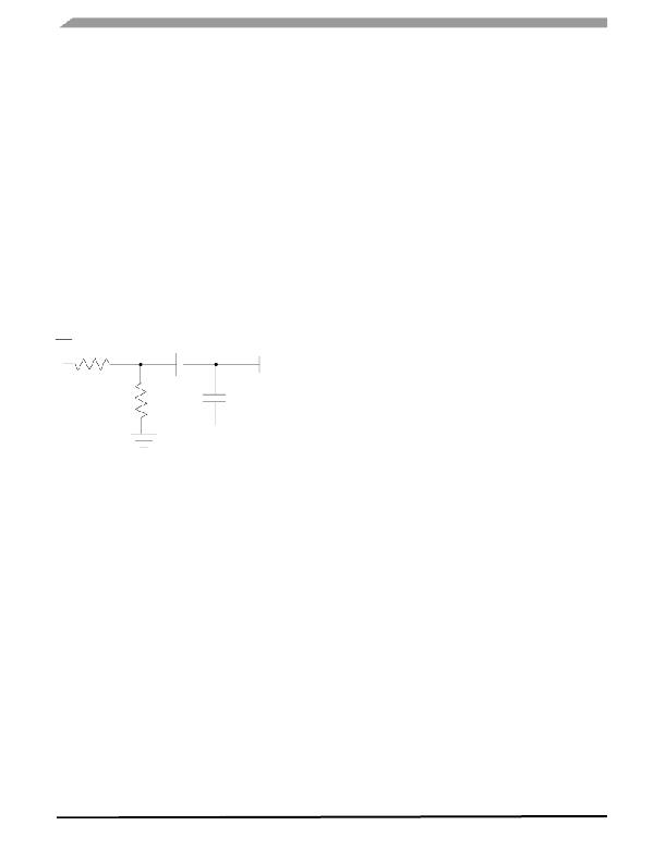
�In� order� to� improve� the� transient� response� of� the� boost,� on�
�the� 34844A,� a� resistor� divider� has� been� implemented� from�
�the� PWM� pin� to� ground� with� a� connection� to� the�
�compensation� network.� This� configuration� should� inject� a�
�1.0� V� signal� to� the� COMP� pin� and� the� Thevenin-equivalent�
�resistance� of� the� divider� is� close� to� R� COMP� ,� i.e.� R� COMP� =� 6.8� k�
�and� R� PCOMP� =� 27� k� for� a� 5.0� V� PWM� signal.�
�PWM�
�C� COMP1�
�3�
�R� SLOPE� =� -----------------------------�
�Variable� Definition�
�D=� Boost� Duty� Cycle�
�V� OUT� =� Output� Voltage�
�V� D� =� Diode� Forward� Voltage�
�V� IN� =� Input� Voltage�
�V� SW� =� V� DROP� of� Internal� Switch�
�Δ� V� OUT� =� Output� Voltage� Ripple� Ratio�
�IIN� AVG� =� Average� Input� Current�
�I� OUT� =� Output� Current�
�r=Input� Current� Ratio�
�IIN� MAX� =� Maximum� input� current�
�IRMS� CIN� =� RMS� current� for� Input� Capacitor�
�IRMS� COUT� =� RMS� current� for� Output� Capacitor�
�L=� Inductor�
�R� PCOMP�
�R� COMP�
�C� COMP2�
�COMP� PIN�
�R� W� =� Inductor� winding� DC� Resistance�
�f� SW� =� Boost� Switching� Frequency�
�CSG=� Current� Sense� Gain� =� 0.2� V/A�
�A� CSA� =� Current� Sense� Amplifier� Gain� =� 9�
�R� SENSE� =� Current� Sense� Resistor� =� 22mohm�
�C� OUT� =� Output� Capacitor�
�V� SLOPE� =� ----------------------------------------------------�
�Slope� Compensation�
�Slope� Compensation� can� be� expressed� either� in� terms� of�
�Ampers/Second� or� as� Volts/Second,� through� the� use� of� the�
�transfer� resistance.�
�The� following� formula� express� the� Slope� Compensation� in�
�terms� of� V/� μ� s:�
�(� Vout� –� Vin� )� ×� CSG�
�L� � 2�
�R� COMP� =� Compensation� Resistor�
�G� M� =� OTA� Transconductance�
�ESR� COUT� =� ESR� of� Output� Capacitor�
�f� RHPZ� =� Right� Half� Plane� Zero� Frequency�
�f� CROSS� =� Crossover� Frequency�
�C� COMP1� =� Compensation� Capacitor�
�C� COMP2� =� Shunt� Compensation� Capacitor�
�V� SLOPE� =� Slope� Compensation� (V/� μ� s)�
�R� SLOPE� =� External� Resistor� for� Slope� Compensation�
�Where� “L”� is� in� μ� H�
�In� order� to� have� this� slope� compensation,� the� following�
�resistor� should� be� set.�
�34844�
�Analog� Integrated� Circuit� Device� Data�
�56�
�Freescale� Semiconductor�
�发布紧急采购,3分钟左右您将得到回复。
相关PDF资料
MC34845AEPR2
IC LED DVR BACKLIGHT 6CH 24QFN
MC34845BEPR2
IC LED DVR BACKLIGHT 6CH 24QFN
MC34848EPR2
IC LED DVR BACKLIGHT 8CH 48QFN
MC56F8006DEMO-T
BOARD DEMO FOR MC56F8006 DSP
MCB1114
BOARD EVALUATION FOR NXP LPC1114
MCB11C14
BOARD EVAL FOR NXP LPC11C14
MCB2470
BOARD EVAL NXP LPC247X SERIES
MCBSTM32EXL
BOARD EVALUATION FOR STM32F103ZE
相关代理商/技术参数
MC34844EPR2
功能描述:LED照明驱动器 BACKLIGHT LED DRIVER W/10 CHANNELS RoHS:否 制造商:STMicroelectronics 输入电压:11.5 V to 23 V 工作频率: 最大电源电流:1.7 mA 输出电流: 最大工作温度: 安装风格:SMD/SMT 封装 / 箱体:SO-16N
MC34845
制造商:SPC Multicomp 功能描述:RECEPTACLE FREE 16WAY 制造商:SPC Multicomp 功能描述:RECEPTACLE, FREE, 16WAY
MC34845AEP
功能描述:LED照明驱动器 6-Ch LED Backlt Driver RoHS:否 制造商:STMicroelectronics 输入电压:11.5 V to 23 V 工作频率: 最大电源电流:1.7 mA 输出电流: 最大工作温度: 安装风格:SMD/SMT 封装 / 箱体:SO-16N
MC34845AEPR2
功能描述:LED照明驱动器 6-Ch LED Backlt Driver RoHS:否 制造商:STMicroelectronics 输入电压:11.5 V to 23 V 工作频率: 最大电源电流:1.7 mA 输出电流: 最大工作温度: 安装风格:SMD/SMT 封装 / 箱体:SO-16N
MC34845BEP
功能描述:USB 接口集成电路 6-Ch LED Backlt Driver RoHS:否 制造商:Cypress Semiconductor 产品:USB 2.0 数据速率: 接口类型:SPI 工作电源电压:3.15 V to 3.45 V 工作电源电流: 最大工作温度:+ 85 C 安装风格:SMD/SMT 封装 / 箱体:WLCSP-20
MC34845BEPR2
功能描述:USB 接口集成电路 6-Ch LED Backlt Driver RoHS:否 制造商:Cypress Semiconductor 产品:USB 2.0 数据速率: 接口类型:SPI 工作电源电压:3.15 V to 3.45 V 工作电源电流: 最大工作温度:+ 85 C 安装风格:SMD/SMT 封装 / 箱体:WLCSP-20
MC34845CEP
功能描述:LED照明驱动器 6-Ch LED Backlt Driver RoHS:否 制造商:STMicroelectronics 输入电压:11.5 V to 23 V 工作频率: 最大电源电流:1.7 mA 输出电流: 最大工作温度: 安装风格:SMD/SMT 封装 / 箱体:SO-16N
MC34845CEPR2
功能描述:LED照明驱动器 6-Ch LED Backlt Driver RoHS:否 制造商:STMicroelectronics 输入电压:11.5 V to 23 V 工作频率: 最大电源电流:1.7 mA 输出电流: 最大工作温度: 安装风格:SMD/SMT 封装 / 箱体:SO-16N